Build A Simple Galilean Refracting Telescope
Note: The easiest way to create the telescope is by looking at past models. If at all possible, get a hold of one, which will be a better teacher than the following instructions ever could.
Building the Telescope Tube
Parts List (With approximate cost):
- Cardboard Telescoping Mailing Tube (1), $3
- Diameter = 50mm (or 2"), Length = 1100mm (or 143")
- Should be comprised of an inner and outer tube with closed ends on the outer tube.
- Concave Convex Lens (the "objective lens") (1), $16 for this and the next lens as a pair.
- Focal Length = 1350mm (0.75 diopter)
- Cut to our specification of 49mm diameter.
- Plano Concave Lens (the "eyepiece") (1)
- Focal Length = -152mm (-6.6 diopter), Diameter = 49mm
- Cut to our specification of 49mm diameter.
Suggested Tools:
- Coping Saw
- Alternatively, any other instrument that will make a relatively clean cut through the mailing tube.
- Drill (bit sizes discussed below)
- Super Glue
- Alternatively, any other kind of glue that will firmly hold the inner and outer mailing tubes together. It must be of a thin consistency.
- Greenlee Punch (optional)
Instructions:
The basic premise of the telescope tube is to align two lenses the appropriate distance from each other. For this telescope, the lenses are a concave convex (one side curved out and the other curved in) and a plano concave (one flat side and one side curved in). The plano concave lens is used as the "eyepiece" with the plano (flat) side facing the eye. The concave convex is used as the "objective lens" that is aligned with the eyepiece and with the convex side facing the sky. Notice that this lens is actually different than the plano convex lens used in the original Galilean telescope, but still gives the same results.
The following design uses pieces of the inner tube of the mailing tube to hold the lenses in place inside the outer tube. This is best illustrated in the following diagram, which shows the cross section of the telescope tube:
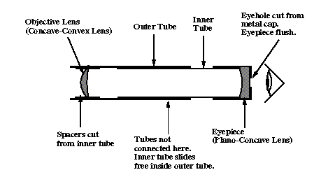
The outer tube of the mailing tube should have a short end that pulls off, and this can be used for the split in the outer tube shown above. This end will be used to hold the eyepiece. The inner tube must have two pieces (about 1" to 1.5" each) cut off of it that will be used as spacers to hold the objective lens in place. Make these cuts as straight and clean as possible, which will be difficult since the tube is made out of cardboard. A coping saw works pretty well for this.
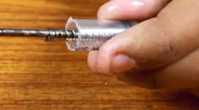
Take the short piece of the outer tube and cut or drill a hole (from 3/16" to 5/16" should be fine) directly in the center of the metal cap on the end. This will be the eyehole. It is important that this hole be as clean as possible (no metal protrusions) so that the the flat side of the eyepiece will fit snugly against the metal cap. An electrician's hole punch or Greenlee Punch works well for this task. If a drill is used, drill with a light pressure, then smooth out the inside surface as much as possible.
Place the eyepiece flush (flat side) against the inside of this eyehole. The large piece of the inner mailing tube left will be used to hold this in place. To do this, drill small holes around the outside of the eyepiece tube. Then, with the eyepiece properly in place, slide the inner tube into it, put glue into the holes, and turn the tube a little bit to spread the glue inside. Hold the tube snugly against the lens inside the cap until the glue dries.
Now, put this aside and take the large outer tube and the two spacers cut from the inner tube. Cut the closed end off of the outer tube, then use the other end to mount the objective lens (since that end already has a clean cut). Again, the "drill holes - put in glue" technique will be used to hold the spacers in place. First, check how far the inner spacer needs to be placed inside the tube so that the lens and other spacer will be able to sit inside the tube comfortably. Then drill holes in the outer tube around this area and glue in the spacer as before.
After the first spacer is in place and dry, place the concave side of the objective lens flush against it, and put the other spacer snugly against the lens to hold it in place (again using the drill - glue method).
Now there are two pieces, each containing one of the lenses. Slide the mailing tubes together as shown in the drawing above, and the telescope is done. By leaving these two pieces unglued, the telescope may be focused simply by sliding the eyepiece part inside the objective part. After a desired magnification/focus is found, the two pieces may be permanently attached (or some tape will give a semi-permanent attachment).
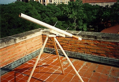
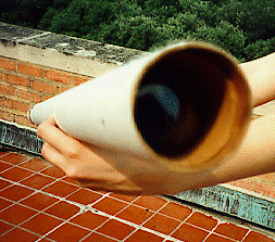
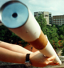
Two images of a finished tube are shown below:
Building the Mounting
The type of mounting that we designed is called an alt-azimuth mounting. It gets its name from the fact that it allows the telescope tube to move in two directions: vertically (altitude), and horizontally (azimuth). Azimuth is defined as the angular distance around the horizon, where north is 0 degrees, east is 90 degrees, and so on. Although many better mountings are available for telescopes, we chose the alt-azimuth design because of it's low cost.
Parts List (With approximate cost for the given quantity):
- Cable Ties (2), $.30
- Must be capable of bundling a diameter of at least 2.5". (About 10.75")
- Cable Tie Mounting Bases (2), $.61
- 2" 10-24 Machine Screw (1), $.15
- 1.5" 10-24 Machine Screw (1), $.10
- 10-24 Wing Nuts (2), $.40
- #10 Washers (4), $.20
- 2" Light Strap Hinges* (3), $3.42
- Should have wood screws included.
- Eye Screws, Open Ended (3), $.24
- 4' Light Chain (1), $1.42
- The chain links must be able to fit on the open end of the eye screws.
- White Wood (But any type of wood should work)
- 2x2x1' (1), $.10
- 1x4x6" (the "base") (1), $.16
- 1x2x4' (the "legs") (3) (or longer if a taller tripod is desired), $1.38
- Metal Hanger**, $.26
Suggested Tools:
- Saw (For wood cutting only)
- Screwdrivers (Type depends on the head of the hinge screws and machine screw heads used)
- Drill with 3/16" drill bit
Total Approximate Price for Mounting: $8.74
Total Approximate Price for the Entire Telescope: $28.00
Instructions:
First, the telescope tube must be mounted. Take the 2x2 piece and find the center of it (on a long side). Drill directly through the center. This hole will be used for mounting the tube assembly onto the tripod. To mount the tube onto the 2x2, take the two cable tie mounts and place them parallel to each other near the two ends of one side of the 2x2 (not on one of the drilled sides). Then lay the tube across these two mounts and use the cable ties to strap it into place.
Next, the tripod must be built. The 1x4 will be called the "base" from now on and will be the most important part in the following instructions. Take the base and screw on the three hinges on one side of it. The hinges should be placed at 120 degree angles with respect to one another (like a peace sign, if that helps with the visual), with the hinged side facing away from the center. The following picture shows how the three hinges should be mounted on the bottom of the base.
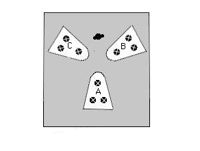
As shown in the diagram above, a 3/16" hole should be drilled between the back hinges, B and C. This hole will be used later for mounting the hanger on the other side of the base. Leave enough room so that one of washers may be placed around the hole and will not touch the hinges. On the other side, make sure the hole is back far enough so that the tube mounting (once mounted on the hanger) will have a great deal of up down movement before hitting the base.
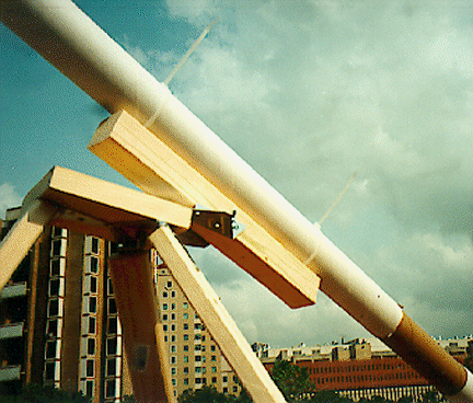
Next, the tripod legs (the 1x2s) can be attached to the hinges, however, pay careful attention to the following instructions first. The hinge on the front (opposite the hole) should have the leg mounted on the outside, so that the top of the leg will hit the bottom of the base when it is pulled out. This is done to provide stability for the hinges, which will otherwise wobble in place. The other two legs should be mounted on the inside of their respective hinges, so that they can be pulled out as far as is desired. When attaching the front leg to the outside of hinge A, leave about 1/8" to 1/4" between the top of it and the base, so that it will be able to pull out some before hitting the base. It is important that this leg hit the base flushly upon its top edge, so be extra careful to keep it straight when screwing it in. If the directions above are not entirely clear, the picture below should give visual clarification. Notice how the front leg is on the outside of hinge A and rests against the bottom of the base. Notice also how the two back legs are attached to the inside of their respective hinges.
One eyescrew should be attached to the inside of each leg about 1/3 of the way down from the base. The chain may then be used to connect them, and will then act as a stop on the legs when they are pulled apart. By adjusting the distance of chain between the legs, the height of the tripod may then be adjusted. When setting up the tripod at any time, make sure the chain is in place and that the legs are all pushed out as far as they will go (especially the front leg, which should have a flush edge against the base when extended), or else the tripod will not be completely stable.
Finally, the 1.5" machine screw and a wing nut (using washers if desired) may be used to attach the bottom of the hanger to the top side of the base. The wing nut should be adjusted to allow a rotational movement of the hanger, thus providing the azimuth movement of the telescope. Do not, however, leave the wing nut so loose that the hanger spins freely.
The 2" machine screw and a wing nut (again using washers if desired) is used to attach the 2x2 through the two sides of the hanger. Again, tighten the wing nut enough to allow movement (this time the altitude movement of the telescope), but to still hold the 2x2 steadily in place.
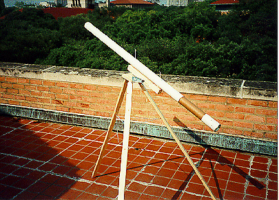
For easy transportation of the telescope, remove the 2" machine screw from the hanger and carry the the tube mounting and tripod separately.
* The hinges used in the original design had the following shape:
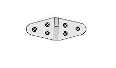
These worked well because they gave a lot of surface area when attached to the tripod legs and base, and could all fit on the base piece. This is not a hard rule though and other types of hinges may be substituted if desired.
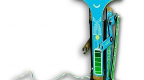
** Improvisation must be used for the metal hanger piece. An example of something that might make a good hanger piece is shown below:
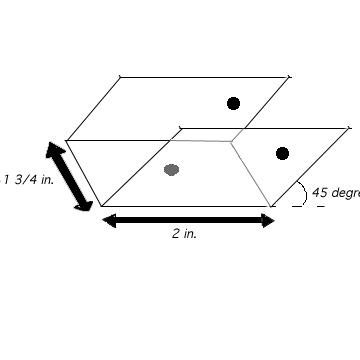
However, a piece that looks like this will not be found in any hardware store. Thus, improvisation must be used for the metal hanger piece. It can either be made from scratch or by modifying some existing item that might work. The important criteria for the hanger are as follows:
- It must be made of sturdy metal, so that the 2x2 will be steadily held in place.
- It must have a base with two sides at 90 degree angles to it.
- The two sides must be 1.75" apart (the size of a 2x2).
- It must have a 3/16" hole drilled into its base so that it can be bolted to the tripod.
- A 3/16" hole must be drilled on each side so that the two holes are aligned. The preferred way to do this is by using a drill press and drilling straight down through the two sides. If a drill press is not available, use a regular drill but be careful that the holes are aligned.
- It must allow freedom of movement when the 2x2 holding the tube is mounted to it. This means that the two holes on the sides must be high enough off of its own base so that the the 2x2 is given a good range of forward/backward movement. Also, it should allow the 2x2 to have good backward movement over the tripod base (preferrably 90 degrees).
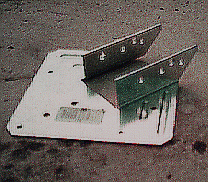
The hanger that was actually used four our telescope was a common hanger called a hurricane tie (available in almost any lumber store). We had to drill the holes ourselves, because none of the pre-drilled holes met the above specifications. The picture below shows the hurricane tie we used for our hanger. The two high holes on the sides and middle hole of the three large holes on the base are the ones that we drilled, all other holes were pre-drilled. The pre-drilled holes on the side would not work with our design because they do not line up across from each other. We drilled the extra hole on the base because it provided the hanger with both stability and a good range of movement.
Comments, Problems, and Suggestions for the Future
The following problems were discovered with our telescope design during our observations and should be looked into by future groups:
- The alt-azimuth mount is by no means the best mount to use for a telescope. It requires movement in two directions to follow a star. An equitorial mounting, however, is aligned with the earth's axis, and must only rotate around its polar axis (which constitutes one degree of movement) to follow a star. The reason we used the alt-azimuth mounting instead of an equitorial was a matter of cost only. If future finances allow or a low-cost design can be created, an equitorial mounting should definately be considered by future groups.
- For the lenses we used, the magnification was only 9 times, compared to a 15 or 20 time magnification that Galileo achieved on some of his telescopes. At the 9 time magnification we had, we were unable to recreate Galileo's observations of Jupiter's moons. Future groups should look for a set of lenses that will better mimic the Galilean telescope.
- Some people in the group had stability problems with the mountings. This is a serious problem, since even the slightest movement of a mounting is bad for observations, especially for our telescopes which had a small field of view. The hinges are not steady in themselves, and it is important that the front leg rest tightly against the base whenever the tripod is set up. Someone had problems with the hanger having a bit too much flexibility and causing the tube to shake. This was an isolated case however, and hopefully if enough of the hanger is allowed to rest on the base, this should not be a problem. If problems like this do occur in the future, than a more rigid hanger should be looked for. Finding new ways of increasing stability should be the top priority of any future astronomy group.
- The height of the tripod was a problem for most people in the group. The given length of the legs does not allow standing or sitting on the ground, but forces one to stand in a half crouch. Future groups should look into a mount that is more height adjustable.
- In the current design, the base tilts back because the front leg remains in a stable position against it while the other two legs are allowed free backward movement. Thus, the back legs to be propped up to allow horizon viewing.
- On one telescope the stick-on mountings fell off of the 2x2. To avoid this problem in the future, groups could use more than two of these, and store the tube in a horizontal position to keep stress off of them.
- The Houston humidity has made the telescopes damp during long periods of observing. A protective plastic wrapping around the mailing tube could prolong the life of the telescope.
- One final suggestion for the future from our group is using teflon washers (or someting similar) between the hanger and the base to allow easier azimuth turning of the telescope tube.
One of the greatest difficulties of observing with a Galilean telescope is the small field of view. This problem is inherent to the design though, and cannot be corrected. Our group did do some measurements to discover the field diameter of the telescopes, and came up with the following numbers:
964.8 arcsec (16.1 arcminutes)
1039.3 arcseconds (17.3 arcminutes)
The differences in the numbers can be accounted for by the fact that everyone sets their magnification differently, so every telescope that we created will have a different field of view.
To do the field of view measurements, find a bright star near the celestial equator with the telescope. Put the star just outside the field of view of the telescope, and measured the time it takes for the star to travel across the field of view, until it is just outside of it. Make sure the star travels directly accross the diameter of the field of view, and not across one of it's chords. The time measurement can then be placed into the following equation, which will give arcseconds when the time is given in seconds or arcminutes when the time is given in minutes:
Field of View = Time[(360)(60)/1436]cos(star declination)
Some of the star declinations for the brighter stars are:
- Betelgeuse: 14.9T
- Rigel: 14.9T
- Regulus: 14.7T
- Sirius: 14.4T
For any star close to the celestial equator, 14.8T will not be too far off.
Source: http://galileo.rice.edu/lib/student_work/astronomy95/telescope_design.html


