Digital RPM meter using simplest technique for kids
By: Engr.Sanwal Saleem
It is consists of light dependent switch, timer (using 555 timer IC), relays, laser, motor and some kind of material for its construction. First the main component is light dependent switch.
Light Dependent Switch(Night switch):
The circuit diagram of Light dependent switch is as follow:

In this circuit the 555 timer IC is used as Schmitt trigger. Here I used Schmitt trigger ,it is also replaced by only one transistor but it is not stable one because the light intensity decreases or increase slowly slowly so this can cause fluctuation so to avoid this I used 555 timer IC which is more stable then any other switch .Another reason for using it is in digital rpm meter I need a quick response of light dependent switch.
LDR is light dependent resistance, when light falls on it its resistance decreases and in dark its show very very large resistance. This circuit works in such a way, In light LDR has less resistance so it has very low voltage drop and this is the voltage through which Schmitt trigger triggered at low voltage it cannot be triggered so in dark its resistance increases and its voltage drop increases and it triggered the Schmitt trigger and it shows out put .
Idea: -
I only know about the light dependent switch .As I explained the working of light dependent switch. In rpm meter the system counts the rounds of motor .it mean that there is a system that after every completion of round of motor its gives pulse which is further counted by another system .I think that this function can also be performed by light dependent switch by using some mechanical parts .
For this project first I check whether the LDR response on laser light or not
And after successful experiment LDR accurately response on laser light
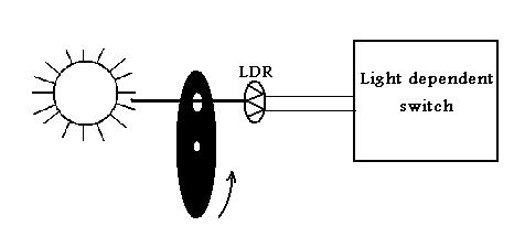
As you see in diagram a disc is placed between LDR and the light source when this disc rotates and after every round of disc when the hole made on disc comes in between light source and LDR and at this instance the light dependent switch responds and give output pulse for just an instance now if I rotate this disc with the help of motor whose rpm is to be measured .when motor rotates the disc we get a sequence of pulses .Now I have to get (rounds per minute ) so I used a timer circuit which switch off the night switch after a minute .So this is the idea used to build digital rpm meter.
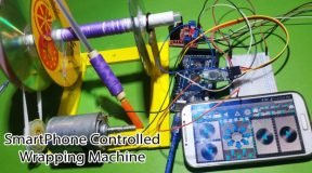
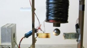
Mechanical Part:-
The mechanical parts consists of following parts
- Compact Disc
- Belt
- Pulleys
- Motor (d.c 12v)
- Drive shaft
- Plastic sheets of 5mm thickness
- Screw driver
- Screws
These are the parts used to make the mechanical parts of digital rpm meter.
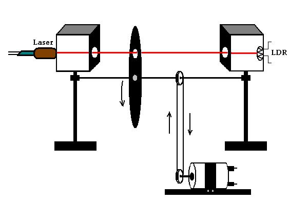
The LDR is covered in a black box so that only laser light falls on it and no other light create distortion .
Calculator:-
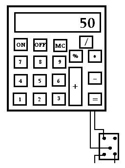
I used calculator for counting the pulses. Actually when any key of calculator is pressed in practical it shorts circuited two wires .Now if we press 1 on calculator and then press "+ " button then after that the equality (=) button is press again and again then increment of 1 is show on display of calculator .Now put out the two wires from the equality button and attached it to the relay which is connected to the out put of light dependent switch. When the disc rotates the light dependent switch give output pulses, which then switch ON and OFF the relay connected to the calculator.
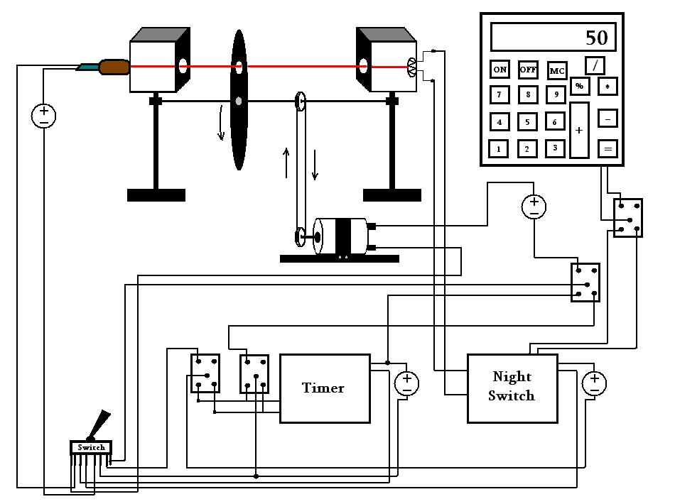
Main Block Diagram:-
The block diagram of digital rpm meter is as follow:
Conclusions:-
In result the display od calculator shows rpm.
Learn Arduino
- Arduino Tutorial in Urdu: Arduino Course for Beginners and advanced
- Arduino tutorial # 1 in Urdu Basics of arduino, installation, configuration
- Arduino tutorial # 2 in Urdu, Introduction to Arduino Board: UNOR3
- Arduino tutorial #3 in Urdu, Multiple Blinking LED on the Arduino
- Arduino tutorial #4 in Urdu, LED’s Controlling with Switches
- Arduino tutorial #5 in Urdu, Servo Motor Controlling with Joystick
- Arduino tutorial #6 in Urdu, Controlling LED’s Wirelessly Via Bluetooth
- Arduino tutorial #7 in Urdu, Experiment with LDR and Arduino
- Arduino tutorial #8 in Urdu, Arduino Controllable Light switch
- Arduino tutorial #9 in Urdu, Arduino Water level Indicator
- Arduino tutorial #10 in Urdu, Distance sensing with ultrasonic sensor and Arduino.